|
Due to the support of our fantastic clients and employees (thanks to all of you), JTT has been “forced” to relocate to a bigger and better facility.
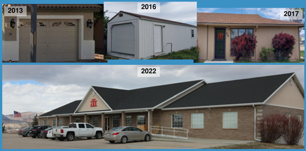
It’s been a journey. When we started in 2013, JTT was only a bench in John’s garage. 2016 was the year we moved to JTT’s first facility—a shed! It was only a year before we burst out of the shed and moved to our first “real” office, where we stayed until moving into our awesome new building in 2022. The new facility gives us ample room to grow, and space to improve our production efficiency (making things is hard when you are cramped!). We are looking forward to being here for a while. But, then again, who knows?  Our primary contract manufacturer for PC boards seemed inadequate for the production tasks regarding our essential products. AMRS decided to investigate a second source and we found with Joshua Tree Technologies exactly what we needed. We were impressed with not only the ability that JTT provided through advanced manufacturing processes and equipment, but the high quality of the end product. JTT pays attention to details during the manufacturing process and we felt confident in their ability to produce the highest quality PC boards that we needed in a timely manner. We have also realized that our other needs like cable harnessing, test equipment, sub-assembly manufacture are easily and capably performed by the JTT manufacturing personnel. Our operations run much more smoothly because of the help JTT provides. We would recommend Joshua Tree Technology to any company looking to improve quality and output in their manufacturing process. Bill Van Wagoner COO-AMRS 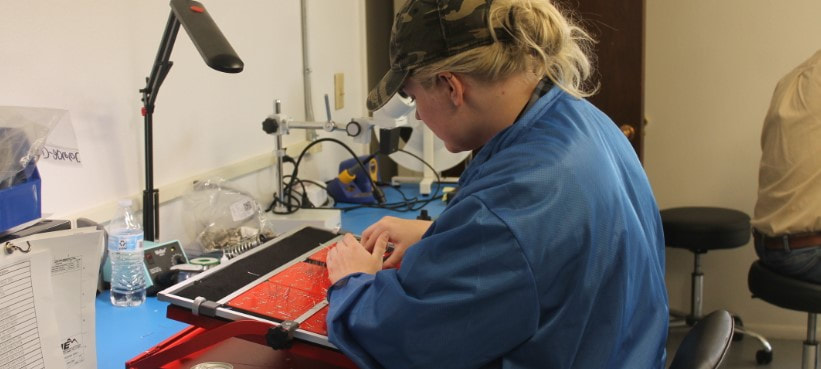 Thanks to ETV for their nice article about JTT... Joshua Tree Technologies: Small Town, Big Technology
By Julie Johansen, ETV News Many have to leave Carbon and Emery counties to find employment after they graduate from high school or receive a degree from a college or university. Dale Curtis was no different. Graduating from Emery High, Curtis attended the University of Utah and received his BSEE (Bachelor of Science in Electrical Engineering). He was interested in the musical field and, after a few stops at other companies, became the Senior Vice President of Research and Development of the Fender Musical Company. Realizing he had climbed to the top, he asked himself “What’s next?” Curtis said he needed to be challenged, so he worked throughout his career in engineering management with several large companies, always with the desire to be back in Emery County where he grew up. Knowing he was not the type to work a physically taxing job, the challenges of employment back home were great. But, in 2010, he made the decision to move back. Upon returning home, Curtis became the general manager for the IEC Division of Intermountain Electronics, a division he founded and helped grow into a multi-million dollar enterprise. He and his team developed a full catalog of world class products and set a new standard of excellence in the market. Now, he is now the President and Co-Founder of Joshua Tree Technologies, LLC. His brother, John Curtis, is also a co-founder of the new business. John is highly experienced in software design for cellular technology, aerospace communications and several other fields. John graduated from Brigham Young University, also with his BSEE. He is tri-lingual, speaking Spanish, Portuguese and English. With the high-speed internet services available in Emery County, John is able to live primarily in Arizona, even though Joshua Tree Technologies is headquartered in Castle Dale. Similarly, while a core few of JTT’s 20 engineers, technicians and designers are located in Castle Dale, most live elsewhere in Utah, Arizona and California; however, they are able to collaborate through the internet. Joshua Tree Technologies could be located nearly anywhere, but its headquarters is found at 70 South 100 East in Castle Dale. It provides research and development services, including product development, technical support and technical management consulting. Their engineers are accomplished veterans who have expertise in electronics, software and mechanical design, all of which are needed to design a wide variety of products. In addition to research and development, Joshua Tree Technologies has a small, state-of-the-art electronics factory in Castle Dale where they do custom manufacturing, including circuit board assembly. In their office, they have converted a conference room into an automated circuit board lab to produce these high technology products. Having both automated and manual assembly techniques allows JTT to specialize in efficient, low-to-mid volume production. This means that while they can build hundreds, or even thousands, of electronic products in a production run, they can still produce even very small quantities for less without sacrificing quality. While attending a local SMTA symposium a few months ago--just before Covid 19 cancelled everything--I found myself in a conversation with a “high-up” from a large contract PCB assembly operation.
When I told him we focus on small to medium production runs, he said something remarkable. He said “We make all our money on the little jobs.” This verifies what I learned over many years as a product developer: Most CMs are geared for big orders, and they penalize smaller orders with much higher prices. We all know it is more costly to produce products in small quantities, but they charge more than the increase in cost justifies! Why? Because they can—as long as the rest of the CM's do the same. We pride ourselves on being the CM that does not do the same. JTT Assembly was founded on the principle of providing good value, even at small quantities. Whether we are making 1, 10, 1000, or more, our prices are based on our actual costs, not what we think we can get. Most of our clients are small or medium sized companies with modest production needs. It may seem old fashioned, but we actually like our clients, and we want them to succeed. This is why we do our jobs, and why we do them the way we do. Don’t expect us to change. Dale Curtis Joshua Tree Technologies  We always enjoy visiting the always-loud-but-cool NAMM show in warm California, and last week's show was no exception. Great to see some of our MI clients (and meet some future clients!) and to spend time with old music industry friends. And it's always great to see products JTT helped develop or assemble on display!  JTT Assembly News: Announcing the launch of our new pick-and-place operation in the JTT Assembly facility in Castle Dale, Utah. This addition will significantly increase JTT's efficiency and capacity for surface mount (SMT) PCB assembly. Now, we can now offer even better value to our contract manufacturing clients! Although still committed to low/mid volume production (at extremely competitive pricing!), JTT can now provide the exceptional value our clients count on at higher quantities than before possible. If you are looking for onshore production without the punitive prices other CMs demand for lower quantities, you owe it to yourself to request a quote from JTT Assembly. You’ll be surprised with what we can do in the USA!  Thanks to all our friends and clients who visited us at the AmCon show in Salt Lake City in October. We had a great time at the show, and enjoyed seeing you again. Of course we also had the pleasure of making many new acquaintances. To our new friends: We're are looking forward to working with you in the future. Let us know what we can do for you! JTT Assembly Solder Standards and Comparison to IPC-A-610 Class 3
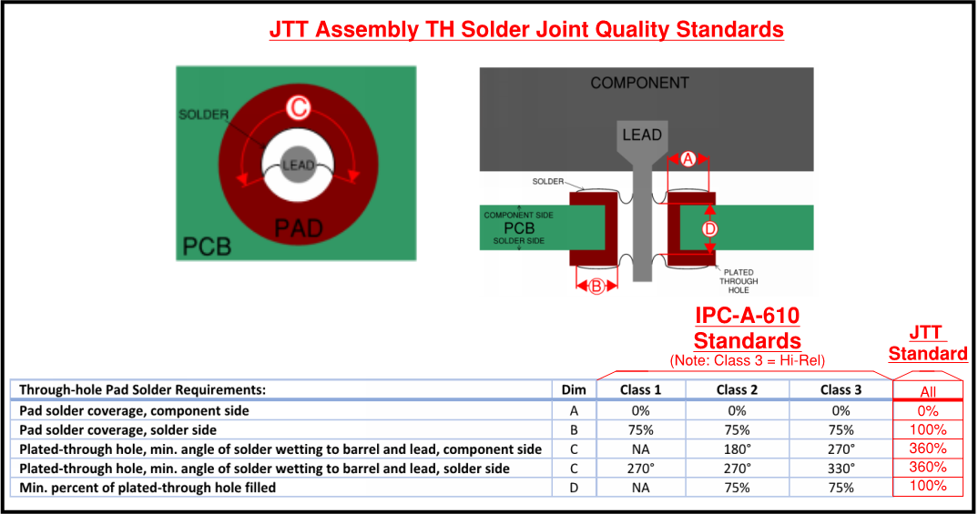
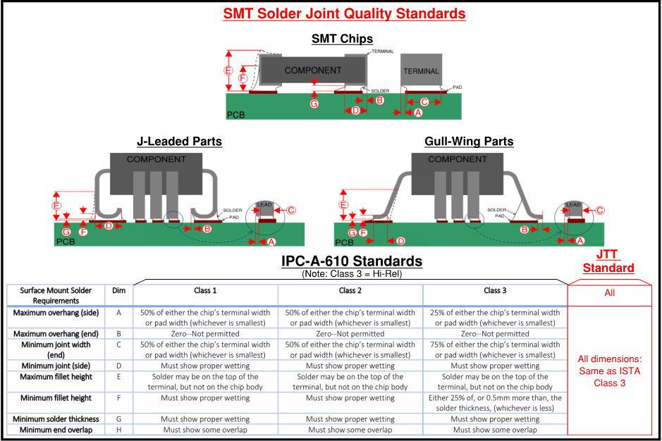
The IPC-A-610 standard provides rules for through-hole and surface mount PCB solder joints, which have been widely accepted throughout the electronics industry. This standard defines three classes, numbered 1 through 3, that are to be applied depending on the level of reliability required. So why three classes? Although it may seem logical to always require Class 3, this level of quality can be expensive to obtain, and the extra reliability may be over-kill in some applications. IPC-A-610 differentiates between the three classes in this way: Class 1 is meant for PCBs used in general-purpose applications. In these PCBs, reliability is important, but so is cost, and Class 1 strikes a balance between cost and reliability that makes sense for products such as inexpensive consumer electronics. At the other end of the spectrum, Class 3 is meant for applications requiring the high reliability, and where cost is much less of an issue. Class 2 (of course) falls between the other classes. JTT Assembly treats every PCB it assembles as though it is destined for a very high-reliability application. In fact, our standards meet, and often exceed the requirements of IPC-A-610 Class 3, as shown below. Following are JTT Assembly’s standards for through-hole and SMT solder joints: New: Automated wire cutting, stripping, terminating: JTT Assembly is happy to announce that our new automated wire preparation line is now operational. With new equipment and our fully trained assembly technicians, we can produce cut, stripped, and terminated wire much faster (5-10x!) than in the past.
And, even more important, the consistency, quality and accuracy of all these operations is even better than it was before. This automation, along with JTT Assembly’s low overhead costs and reliable quality, translates to even more value for our customers of wireset and cable assemblies. And, as always, all of JTT Assembly’s work is done in the USA! 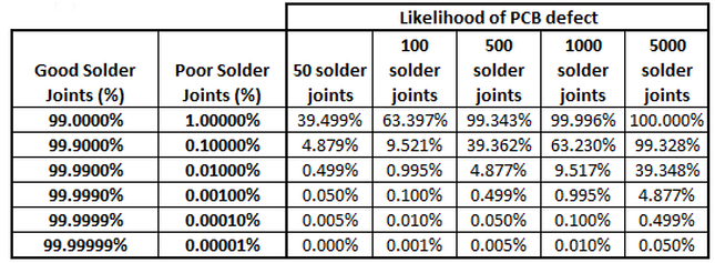 The Basics of Solder Joint Quality D. Curtis Soldering quality is a topic that gets much less attention than it deserves. This is something I realized later than I should have. After being in the electronics industry for years, I was heading up an R&D group for a large company that sold hundreds of electronic products every day. In this role, one of my responsibilities was to review warranty repair claims to see what caused certain products to fail. Overall, our products were doing well, and the number of field failures was within industry norms. This was reasonably good news, but, in my view, it didn’t mean we couldn’t do better, so, I started reviewing tall stacks of failure reports from our service centers. With years of data to review, this looked like a daunting task, but it didn’t take long to discover something shocking. Over half of the product failures stemmed from a single cause: bad solder joints. Clearly, the quality of soldering is something that should not be ignored. Likelihood of Failure Considering how many solder joints are on a typical PCB, and knowing that it only takes one bad joint to cause a failure, it’s easy to see why solder quality has such a great effect on reliability. This is shown in the table below: Because of the large number of solder joints on most PCBs, solder quality levels that may seem reasonable (well above 99% quality), are actually inadequate. To illustrate this, let’s interpret some of this data:
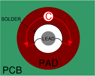
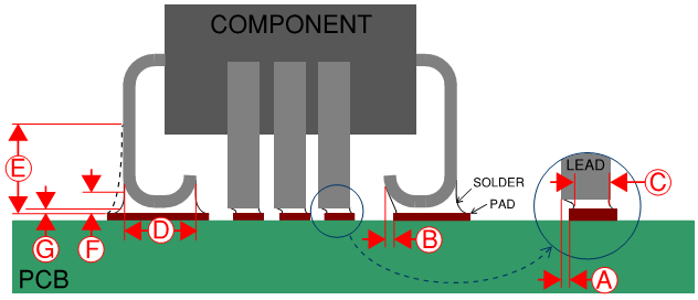
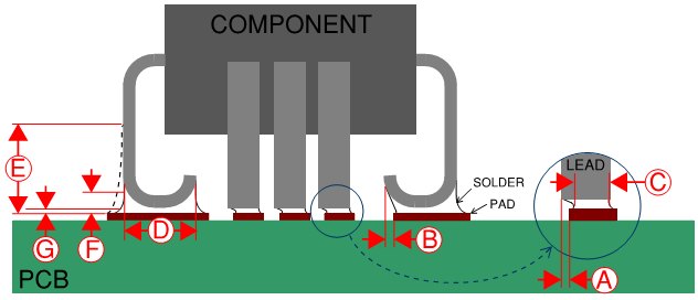
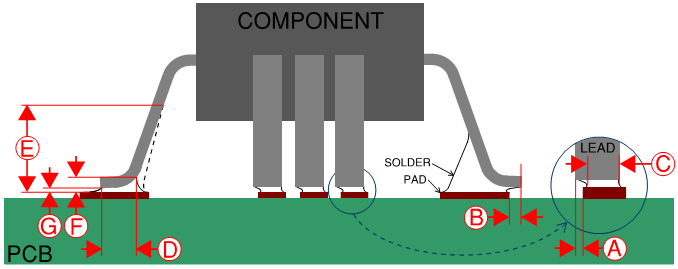
The statistics are clear--to consistently produce good PCBs, the soldering process must be virtually perfect. What is a Good Solder Joint? Evaluating the quality of the soldering process requires a method of differentiating between good solder joints and bad ones--preferably without having to wait for a circuit failure to happen. Fortunately, there are well-established rules and standards that can be used to visually measure the quality of a solder joint, and these measurements are very excellent indicators of solder joint reliability. The first rule is that the solder should have a shiny, smooth surface. A dull or rough looking surface generally indicates a brittle solder joint, without good “wetting” of the solder to the pad or the lead. (In this context, “wetting” refers to the solder flowing and bonding to the lead and pad.) A solder joint without a shiny and smooth surface is called a “cold” solder joint and is likely to result in a failure. With modern environmental rules (e.g. RoHS), leaded solder is no longer allowed in most applications, and. sadly, the alternatives are not as easy to use. Melting temperatures are usually higher, and the solder tends to not wet as easily. As a result, lead-free solder joints are not as nice looking as the beautiful, leaded solder joints we used to expect and that are missed by people, like me, who have been soldering for years. However, a good lead-free solder joint still has a reasonably smooth and shiny surface, especially compared to that of a cold solder joint. In addition to the appearance of the solder finish, the location and quantity of the solder must also be taken into consideration. There must be enough, but not too much, solder in the right places in order to ensure good conductivity and mechanical strength. The IPC-A-610 standard provides rules for through-hole or surface mount PCB solder joints, which have been widely accepted throughout the electronics industry. This standard defines three classes, numbered 1 through 3, that are to be applied depending on the level of reliability required. Class 1 of the standard is for general-purpose PCBs, while classes 2 and 3 are used when higher reliability is required. While it may seem wise to always demand class 3 to get the highest reliability, this comes at a significant cost. There is a point where reliability and economics balance. Where this point is depends on the application, and this is the reason there are three separate classes in the IPC quality standard. An inexpensive consumer gadget, such as a remote control that will be obsolete in a year or two, has a different balance than a life-saving medical device like a pacemaker. PCBs can have surface mount solder joints, through-hole solder joints, or both. For each type, the IPC specification provides rules to visually determine the quality of these solder joints. The standard also includes requirements beyond solder joints, such as PCB design rules, but in this article, we will only consider the requirements for solder joints. Through-Hole Solder Joints A through-hole solder joint includes the component lead, solder pads on each side of the PCB, and a plated-through hole, sometimes called a barrel. The component lead protrudes through the plated-through hole. The cylindrical wall of the plated-through hole and the pads, which surround the entrance and exit of the hole, are made of copper and provide a surface for solder to bond to. The IPC standards for through-hole solder joints include requirements for how much of the pads are covered with solder on the two sides of the circuit board (component side and solder side), and how much of the plated-through hole is filled with solder. In an ideal world, it would be nice to have 100% of the pads covered with nice “chocolate kiss” shaped solder fillets on both sides of the PCB, and to have the plated-through hole entirely filled with solder. (A “fillet” is the shape of the solder on the pad after the lead has been soldered in place. On a through-hole solder joint, a good fillet looks sort of like a round, melted pyramid, or the popular candy.) Though ideal solder joints are the goal, perfection is not required for reliability, and it is expensive to obtain. Even case 3 of the IPC standard, with its tough requirements intended to ensure very high reliability, does not require perfection. So, what is required for reliability? Let’s start with solder coverage of the pads on both sides of the PCB. On the solder side, the pad should be mostly covered with solder. All three IPC classes require 75% solder coverage of the total pad’s area. On the component side, however, solder coverage of the pad is much less important, and coverage here is not required in the IPC standard. The IPC standard also sets the minimum for how much solder is in the plated hole. First, solder must be wetted to both lead and the inside wall of the plated-through hole through a minimum angle of the hole. This is illustrated in the figure below: Figure 1A: Through Hole Solder Joints, Top View: For IPC classes one and two, the minimum angle on the solder side is 270 degrees, with class 3 requiring 330 degrees. Once again, the rules for the component side are much less demanding: There is no requirement for Class 1, and classes 2 and 3 require 180 and 270 degrees respectively. There are also IPC standards for how much of the plated-through hole is filled with when viewing the hole from the side, as shown in the figure below. Figure 1B: Through Hole Solder Joints, Side View Class 1 does not require any solder in the plated-through hole. Class 2 and 3, on the other hand, require that the solder fills a minimum of 75% of the hole. This table summarizes the IPC requirements for through-hole solder joints, as described above: Table 1: Through Hole Solder Joint Requirements Following these rules and standards ensures that the through-hole solder joints will be reliable to the levels intended by the IPC standard. Surface Mount Solder Joints for Chips Although there are similarities, such as the requirement for a smooth, shiny surface, the requirements for good surface mount solder joints are different from those of through-hole joints. Surface mount solder joints also have rules set by the IPC-A-610 standard. Once again, these requirements are accepted in the electronics industry, and the three reliability classes of the IPC standard apply. For chip components, the IPC standard defines limits for the placement of the chip on its pads and for the location of the solder. These requirements are described by the figure and table below. Figure 2: SMT Chip Solder Joints Table 2: SMT Chip Solder Joint Requirements Surface Mount Solder Joints for J Lead and Gull Wing Components The following figures and tables describe the IPC standards’ rules for each reliability class for J lead and gull wing components: Figure 3: J-Lead Solder Joints Table 3: J-Lead Solder Joint Requirements Figure 4: Gull Wing Solder Joints Table 4: Gull Wing Solder Joint Requirements “What We Measure, We Improve”
This is an old and well-known adage, used often because of the truth it holds. Another version, attributed to Peter Drucker, is that “You can’t improve what you can’t measure.” If the quality of solder joints on a PCB is important, (and it is very important), then having a way to measure quality is just as vital. The measurement method must be predictive—the “wait to see how many fail” method of measuring quality is possible, but certainly not practical or profitable. Conclusion The standards and rules described here provide non-subjective, repeatable measurements for the quality of solder joints on PCBs. These standards are time-tested, and, crucially, are well known to be predictive of product reliability. Just as importantly, these standards are well accepted throughout the electronics industry. This means realistic expectations can be set, and quality can be demonstrated, without subjective argument and with confidence in a level of reliability (and expense) appropriate for the application. |
Details
Archives
August 2021
Categories |
|
Contact us today at: Contact_JTT@joshuatreetechnologies.com
Vertical Divider
|
Vertical Divider
|






 RSS Feed
